|
|
| I have invented a device that can be classified as a permanent magnetic
motor. The object of this invention is to show that a magnetic motor can
be built that will power itself and produce extra voltage to be able to
power an external load.
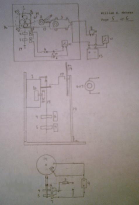
Advantage The advantage of this device is that it can produce electricity with no external input. It is not area specific, does not require wind, hydro, sunlight, petrol fuel or any other other product or products to work. It is a totally closed loop system. History The problem with these types of inventions has been that electrical energy must be created on a immediate and on going basis to run the device. Usually a number of permanent magnets are attempted to be configured to cause rotation. Up to one rotation can be achieved but when the magnet return to its original point it gets stuck. This has been referred to as "the sticky point". At this point it requires more power than can be generated by the one rotation to start the magnet moving again. Even spinning the magnet(s) at high speed which may cause it to appear to be functioning will in time slow down and stop. Operation I am using a 30 day mechanical clock movement to swing permanent
magnets thru a coil to produce an emf. The emf is stored in a bank of capacitors
which can then be discharged into a 12 volt deep cycle battery via a pulsing
method to keep the battery fully charged. The invention is totally scaleable.
In such that the performance can be greatly increased by:
What is unique about this invention is that the force required to move the magnets through the coils is totally independent of the magnets. The definition of a permanent magnetic motor is that it can produce enough energy to run itself without the aid of any external input. This design meets these criteria. When the magnet swings in and out of the coils it will produce a negative and positive indication on a voltmeter. The negative side is connected to a germanium IN-34 diode. This diode is used because unlike a standard signal diode which exhibit a 0.7 (and higher) forward voltage drop the IN-34 exhibits on around a 0.2 dc voltage drop. This allows more emf into the capacitor to charge the capacitor faster. The diode only allow electricity to pass on one direction so only the positive emf flows into the capacitor. The capacitor is a 50 volts 1000uf electrolytic air foil capacitor. Exhibits fast emf build up and very little leakage. The negative side of the capacitor is connected to the clock body. The reason for this is that there is a hand connected to the hour hand shaft witch when rotating will complete the circuit by moving over the plastic disk. On the disk are any number of copper (or like) strips that when the hand touches them will complete the circuit to charge the capacitor. The capacitors(s) will then be pulsed into a 12volt deep cycle motor cycle battery after a total of 16-20 volts dc have been stored in the capacitors. Since a bank of capacitors will store the 16-20 volts it will take approx. 15-20 banks to pulse the battery the required number of times to keep it charged up. The average charge per capacitor is around 700mv. Thus to store a one time pulse charge would require around 22 capacitors per bank. Or as many as 400+ capacitors. Once the motor is energized by the battery it needs to run for approx. 12 seconds to totally rewind the 30 day main spring. The motor under the load of rewinding the main spring draws around 4.7 amps. The uniqueness of this invention is that the motor only has to be on for 12 seconds per month. But the clock pendulum swinging just these 2 coils can produce approx. 600 mv pr minute. This equates out to:
Example: If the invention was charging the capacitor at around 26 volts/pulse there would be enough stored voltage to pulse the battery approx. 1000 times. The pulse rate should be a 1 pulse per second. Or one could pulse for over 16 minutes to charge the battery. It only takes about 4 minutes to recharge the battery when it has been running the motor for 12 seconds. The voltage drop on the battery is around 80 mv. But after about an hour the voltage will recover 40 plus millivolts. Due to the unique chemical properties of a deep cycle lead acid battery. The deficit voltage of around 40 mv is equally charged up by the pulsing method in about 3-4 minutes. Thus the invention can run itself as well as store excess energy. Drawings
List Of Parts Parts List
Additional Information 1. Time it takes clock hand to make one complete revolution is 75 minutes. 2. Time it takes for hand to move over the 7 copper strips closing the circuit to charge a bank of 7 capacitors is 11 minutes. About 1.6 minutes per cap. 3. Average voltage per capacitor stored is .575 to .725 volts. 4. Pulsed a charged capacitor from the device across a 600 ma meter. Pegged the meter! No resistive load used. But this is what is required to charge the battery. This was with one cap! Do the math there is sufficient voltage and amperage generated to do the job with a lot left over. Much more amperage than I thought would be there.-Great news!! 5. Need to design a mechanical switching unit to be able to discharge a bank of capacitors (around 16-20) into the battery-the pulse need to charge the battery, only an engineering problem. 6. Will now begin to put the full number of capacitors on the to complete the charging cycle. 7. The battery shown in the video is connected to the motor it is in no way running the clock or generating the electricity stored in the caps. |
| Bill Mehess
(503) 366-9135 |