Title of Invention:
Pinwheel Turbine
Pin Wheel Turbine Patent Application 10-637903
Name of Inventor:
Robert William Jackson
A Citizen of the United States of America
Address of Inventor:
3309 Jomar Drive
Plano, Texas 75075
Prior Address of Inventor: RR 2, Box 142
Hinton, Oklahoma 73047
CROSS REFERENCE TO RELATED APPLICATION
This application is based on the following provisional patent application.
Title: Pinwheel Turbine
Patent Number 60/409171 Filing Date: 9-9-2002
The application related to the following provisional patent
Title: Municipal Hydroelectric Power Generator Patient Number 60/402424
Filing Date: 8-10-2002
This application is related to the following provisional patent
Title: Self-Powered Hydroelectric Generator Patent Number 60/363271
Filing Date: 3-11-2002
This application is related to the following provisional patent
Title: Self-Powered Air-Driven Electric Generator Patent Number 60/368394
Filing Date: 3-29-2002
This application is related to the following non-provisional application
Title: Self-Powered Hydro-Electric Generator Patent Number 10/136521
Filing Date: 5-1-2002
This application is related to the following non-provisional application
Title: Self-Powered Air-Driven Electric Generator Patent Number 10/136063
Filing Date: 5-1-2002
Robert William Jackson requests that Disclosure Document number 506280
also be included in the examination of this application. Title:
Self-Powered Hydro-Electric Generator. Filing Date: 2-28-2002.
Robert William Jackson requests that Disclosure Document number
514683 also be included in the examination of this application. Title:
Emergency Hydro-Electric Generator. Filing Date: 7-8-2002.
Robert William Jackson requests that Disclosure Document number
512933 also be included in the examination of this application. Title:
Municipal Water Supply Generator System. Filing Date: 6-6-2002.
STATEMENT REGARDING FEDERALLY SPONSORED RESEARCH OR DEVELOPMENT
"Not Applicable"
REFERENCE TO SEQUEL LISTING, A TABLE, OR A COMPUTER PROGRAM LISTING
COMPACT DISC APPENDIX

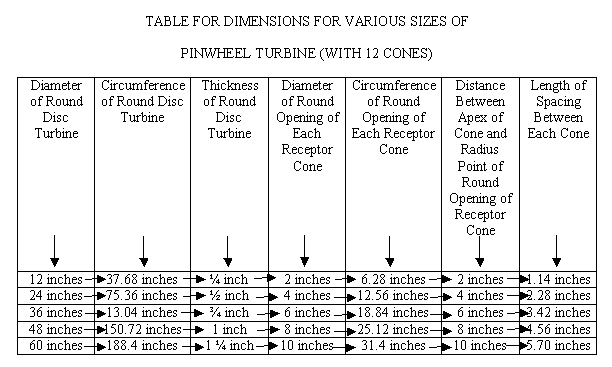
TABLE FOR DIMENSIONS FOR VARIOUS SIZES OF
PINWHEEL TURBINE (WITH 12 CONES)
Diameter of Round Disc Turbine Circumference of Round Disc Turbine Thickness
of Round Disc Turbine Diameter of Round Opening of Each Receptor Cone Circumference
of Round Opening of Each Receptor Cone Distance Between Apex of Cone and
Radius Point of Round Opening of Receptor Cone Length of Spacing Between
Each Cone
12 inches 37.68 inches ¼ inch 2 inches 6.28 inches 2 inches
1.14 inches
24 inches 75.36 inches ½ inch 4 inches 12.56 inches 4 inches
2.28 inches
36 inches 13.04 inches ¾ inch 6 inches 18.84 inches 6 inches
3.42 inches
48 inches 150.72 inches 1 inch 8 inches 25.12 inches 8 inches 4.56
inches
60 inches 188.4 inches 1 ¼ inch 10 inches 31.4 inches 10 inches
5.70 inches
BACKGROUND OF THE INVENTION
This invention deals with generating electricity. This turbine
could be used with most generators in use today.
I thought of this design for this turbine on the 4th of July
2001. I noticed the efficiency of the rotation of a pinwheel firework.
At the time I had some ideas about generating electricity with water and
air. I combine the concepts and developed some plans. I started
a timeline on October 15, 2001, dealing with these concepts and this particular
turbine. I documented my efforts by mailing information to myself.
On or around January 21, 2002, I attempted to get a provisional
patent. I met with 2 different patent attorneys and called many more.
One of the patent attorneys said he would help me if I had a
drawing made up. I was confused. I thought a drawing was required.
It took about a month for a mechanical engineer to get this project done.
I ordered the patent kit from the patent office around 1-23-2002.
It took over 2 weeks to get to me. I mailed a Disclosure Document
on 2-11-2002 that deals with this turbine. Filing date 2-28-2002.
Document number 506280.
After paying the lawyers and mechanical engineer fees I didn't
have enough money to hire the lawyer to submit my provisional patent.
I submitted my own patent application. Filing date 3-11-2002,
patient application number 60/363271. This patent application is
the first one on file for me that deals with this turbine. I list
this turbine in numerous other applications. I believed this
turbine is unique and is a good design.
BRIEF SUMMARY OF THE INVENTION
This is a high pressure turbine. This design is for high PSI (Pounds
per Square Inch) pressure coming from either air or water. The theory
is to create the most RPM's (Revolutions Per Minute) with this thrust of
pressure in the most efficient manner.
This turbine needs to be attached to a generator in which RPM's
determine power output. I call this turbine the pinwheel because
of its basic design is pattern after this firework. This design has
12 receptor cones.
BRIEF DESCRIPTION OF THE SEVERAL VIEWS OF THE DRAWING
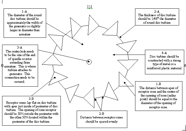
1-A – Diameter of disc dimensions
2-A – Thickness of disc turbine
3-A – Center hole dimensions
4-A – Material used in making of Pinwheel Turbine
1-B – Receptor cone dimensions
2-B – Spacing between receptor cones
3-B – Position of receptor cones
DETAILED DESCRIPTION OF THE INVENTION
0001 The basic design is patterned after the pinwheel firework.
My design is a solid disc. This disc should have 12 receptor cones
positioned around the perimeter (circumference) of the round disc (See
chart on page 5). These receptors should be spaced evenly (see 2-B).
0002 The turbine should be constructed with a strong metal or a reinforced
plastic material (See 4-A).
0003 The diameter of the round disc turbine should be approximately
the width of the generator or slightly larger in diameter than Armature
(See 1-A). This is calculated when turbine is vertical and generator
is horizontal or turbine is horizontal and generator is vertical.
The spindle or rotor extending from Armature should be center point for
measuring this dimension. This is where turbine attaches to generator.
0004 The thickness of disc turbine should be 1/48th the diameter of
round disc turbine (see Box 2-A).
0005 The center hole needs to be the size of the end of spindle or
rotor that extends from Armature. This is where turbine attaches
to generator. This connection needs to be secured. (See 3-A).
0006 The center hole should be approximately 1/10 the diameter of disc
turbine, but this could vary due to size of generator to which it is attached.
0007 The distance between apex of receptor cone and the center of the
opening of cone (radius point) should be equal to the diameter of the opening
of
receptor cone. (See 1-B)
0008 Receptor cones lay flat on disc turbine with apex just inside
of perimeter of disc turbine. The opening of cone receptor should
be 50% outside the perimeter with the other 50% located within the perimeter
of the disc turbine. (See 3-B)
0009 The disc turbine and the receptor cones needs to be either one
solid object or receptor cones needs to be securely attached to round disc
turbine.
00010 This turbine is similar to the Pelton hydro-electric turbine.
I claim my turbine is different because I use cones instead of buckets
as the receptors. This is the only turbine that is similar to mine
that I'm aware of.
CLAIMS
(1) I claim this turbine can be used with the thrust of air or water.
(2) I claim this turbine can be adapted and can be used with most generators
on the market today.
(3) I claim this turbine can be used with a newly designed generator.
ABSTRACT OF THE DISCLOSURE
I designed this turbine to be used with pressure (thrust) from
water that emits from water pumps or air that emits from air compressors.
This pressure (thrust) is directed at point of turbine which creates the
most efficient rotation (RPM's) of turbine which is attached to a generator.
 BOXES FOR DRAWING
Box-1-A-The diameter of the round disc turbine should be approximately
the width of the generator or slightly larger in diameter than armature.
Box-2-A-The thickness of disc turbine should be 1/48th the diameter
of round disc turbine.
Box-3-A-The center hold needs to be the size of the end of spindle
or rotor extending from armature. this is where turbine attaches
to generator. This connection needs to be secured.
Box-4-A-Disc turbine should be constructed with a strong type of metal
or a reinforced plastic material.
1-B-The distance between Apex of receptor cone and the center of the
opening of cone (radius point) should be equal to the diameter of the opening
of receptor cone.
2-B-Distance between receptor cones should be spaced evenly.
3-B-Receptor cones lay flat on disc turbine with apex just inside of
perimeter of disc turbine. the opening of cone receptor should be
30% outside the perimeter with the other 50% located within the perimeter
of the disc turbine.
|

