|
|
|||||||||||
|
|
|||||||||||
|
MOBLAS 4 Satellite Laser Ranging (SLR) Station Mt. Laguna, California +32° 52' 34.46", -116° 24' 54.18" ..
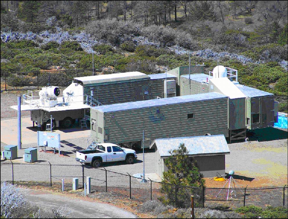
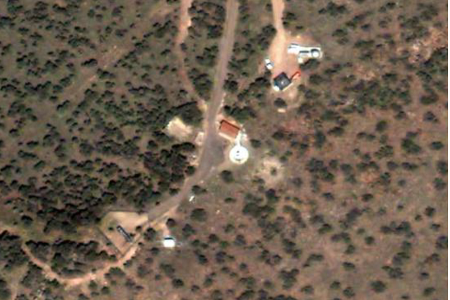
The MOBLAS-4 system is located on Mt. Laguna, California at a NASA GSFC site, in cooperation with the California Cleveland National Forest Service. This is a remote site situated about one hour east of San Diego with limited communications and self sufficient metropolitan services. The MOBLAS-4 compound is also home to other scientific observational systems such as the Scripps Orbit and Permanent Array Center (SOPAC) permanent Global Positioning System station, the soon to be upgraded EarthScope geophysical station, and the soon to be constructed Doppler Orbitography and Radiopositioning Integrated by Satellite Precise orbit determination and location system (DORIS). Previously, the MOBLAS-4 system used a commercial 56 kilobit data communications line to transmit an average of 120 kilobytes of tracking data per hour, with an approximate peak of 265 kilobytes, using File Transfer Protocol (FTP). Each hour, the Lynx based data processing computer automatically transmits satellite laser ranging data. This data communications line is also used by the three person crew to send text based system status reports once per shift, monitor weather conditions every few hours for several minutes, communicate with NASA SLR Headquarters in Greenbelt, Maryland, communicate with other SLR systems throughout the world using electronic mail, and to maintain the MOBLAS-4 site via a Windows based desktop computer. The NASA SLR Program engineering staff in Greenbelt, Maryland uses the communication line, via FTP and Telnet, to troubleshoot software anomalies, investigate hardware problems, and upgrade system software. The engineering staff communicates with the data processing computer mentioned above as well as the controller computer. Unfortunately, the commercial communications service had been relatively slow with network connections intermittent. The service is many times interrupted during data communications and system functions, requiring repeated data transmissions and delayed system operations. The 56 kilobit service is also used by the MOBLAS-4 crew to periodically communicate with the sponsors of the other geophysical experiments taking place at the MOBLAS-4 site, such as SOPAC, EarthScope, and DORIS. The NASA MOBLAS-4 site is home to several other geophysical experiments, one of which is already part of the HPWREN alliance, EarthScope. The following are pictures of the MOBLAS 4 during daytime and can be seen in the view of the HPWREN Mt. Laguna West camera. High Performance Wireless Research and Education Network (HPWREN)
..
|
|||||||||||
|
MOBLAS 5 Satellite Laser Ranging (SLR) Station Yarragadee, Dongara, Australia -29° 2' 47.00", +115° 20' 48.00" ..
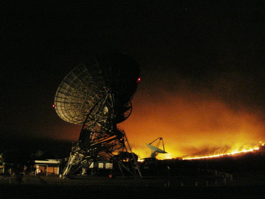
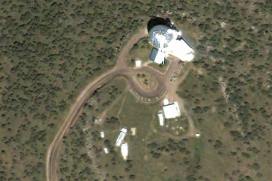
The Moblas 5 (Yarragadee) SLR facility is located 100 kilometres south east of Geraldton, Western Australia, on the Yatharagga property. The observatory plays an important part in the Australian and International geodetic framework and has been operational since 1979. The observatory is near the Universal Space Networks (USN) Radio Telescope. The MOBLAS 5 Observatory and the US Navy Telescope are displayed in this aerial view image. The Moblas 5 (Yarragadee) SLR facility is one of two SLR units managed by Geoscience Australia and currently operated under contract by Electro Optic Systems (EOS). The second facility is at Mt Stromlo near Canberra. NASA operates a number of Moblas facilities around the world and owns the MOBLAS 5 equipment. New SLR2000 equipment is being developed by NASA. MOBLAS 5 equipment
At the Moblas 5 site there are also GPS and GLONASS receivers along with a DORIS transmitter and time reference equipment. This image displays a close view of some of the Observatory's equipment. SOURCE: MOBLAS 5 Satellite Laser Ranging (SLR) Station EOS - Electro Optics System Moblas 5 Satellite Laser Ranging Station, Yatharagga
Ron Thompson, Group General Manager
Contact Details:
Telephone: + 61 8 9929 1011
Related Links:
|
|||||||||||
|
MOBLAS 6 Satellite Laser Ranging (SLR) Station Hartebeesthoek Radio Astronomy Observatory Johannesburg, South Africa -29° 2' 47.00", +115° 20' 48.00" ..
This is a 9m antenna Operated by Intelsat. Used for TTC and Launch tracking. -25° 54' 28.34", +27° 41' 56.48" ..
MOBLAS-6 station in Hartebeesthoek, South Africa are already very important contributors to the network. The station in Hartebeesthoek provides the first multi- technique fundamental station in the region with GPS and VLBI. The Hartebeesthoek Radio Astronomy Observatory (HartRAO) is located west of Johannesburg, South Africa. It operates as a National Research Facility under the auspices of the National Research Foundation (NRF). Hartebeesthoek Radio Astronomy Observatory
-25° 53' 10.58", +27° 42' 26.76" The Hartebeesthoek Radio Astronomy Observatory (HartRAO) is a radio astronomy observatory located in a natural bowl of hills at Hartebeesthoek just south of the Magaliesberg mountain range, Gauteng province, South Africa, about 50 km west of Johannesburg. It is a National Research Facility run by South Africa's National Research Foundation and is the only major radio astronomy observatory in Africa. SOURCE: Wikipedia
-25° 53' 23.30", +27° 41' 7.04" ..
-25° 54' 35.70", +27° 42' 36.19" ..
..
..
|
|||||||||||
|
MOBLAS 7 Satellite Laser Ranging (SLR) Station Goddard Space Flight Center, Greenbelt, Maryland Good Luck Road, Beltsville, Prince Georges County +32° 52' 34.46", -116° 24' 54.18" ..
..
+39° 1' 15.62", -76° 49' 40.16" ..
+39° 1' 15.62", -76° 49' 40.16" ..
+39° 1' 15.62", -76° 49' 40.16" ..
+39° 1' 17.94", -76° 49' 27.49" ..
+39° 1' 17.94", -76° 49' 27.49" ..
Left - +39° 1' 19.17", -76° 49' 36.06" - Right - +39° 1' 21.24", -76° 49' 28.03" ..
..
..
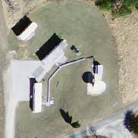
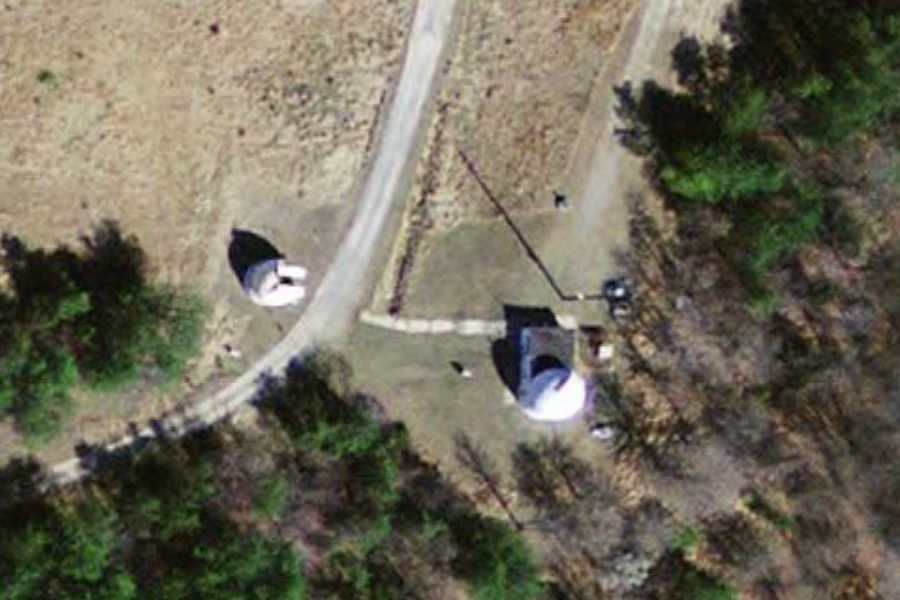
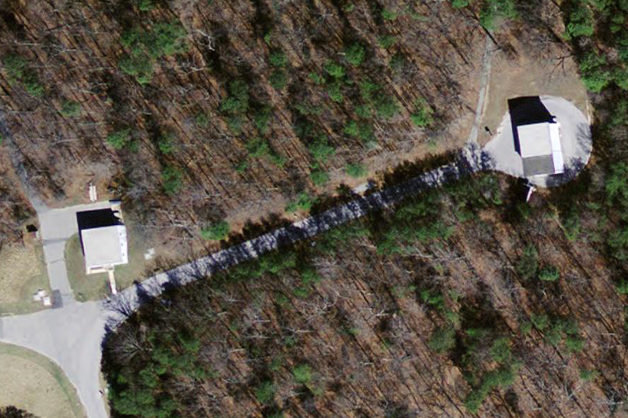
The prototype system SLR 2000, SLR station being developed at the Goddard Optical Research Facility (GORF) at the NASA Goddard Space Flight Center (GSFC) in Greenbelt, Maryland, is currently in the testing phase. There is also a nighttime tracking view in which the pulsed laser beam is visible. A network of similar stations distributed around the world would be used for laser ranging to GPS satellites. The Mobile Laser System MOBLAS-7, the most accurate SLR system in the world, is stationed at the Goddard Geophysical and Astronomical Observatory (GGAO) to perform three vital NASA Satellite Laser Ranging (NSLR) network functions:
Space Communications and Navigation (SCaN) - NASA - SECURE Password Required |
|||||||||||
|
Goddard Solar Power Array Goddard Space Flight Center, Greenbelt, Maryland Good Luck Road, Beltsville, Prince Georges County +39° 1' 50.77", -76° 49' 26.56" ..
|
|||||||||||
|
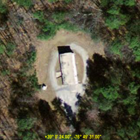
Spacecraft Magnetic Test Facility Goddard Space Flight Center, Greenbelt, Maryland +39° 0' 24.00", -76° 49' 31.00" ..
The Spacecraft Magnetic Test Facility at the Goddard Space Flight Center in Greenbelt, Maryland was built in 1966 to allow the evaluation of magnetic movement in spacecraft. The building is constructed on non-magnetic materials and contains a magnetic coil system that allows the cancellation of the Earth's magnetic field. This unique building was designated a National Historic Landmark in 1985 - Wikipedia
+39° 0' 8.01", -76° 49' 22.03" ..
..
Property Name: Spacecraft
Magnetic Test Facility
Description: The Spacecraft Magnetic Test Facility was built in 1966 and consists of a 60-foot square building constructed of nonmagnetic material, which contains a 42-foot diameter coil system. The coil, a 3-axis Braunbek system of 4 loops on each axis, provides cancellation of the earth's magnetic field over the central 6-foot diameter spherical volume, uniform to 0.001% and stable to a half nanotesla. Geomagnetic fluctuations up to 16 Hz and +/- 750 nanoteslas are eliminated by automatic servo-control from 3 remotely located rubidium magnetometers. The coil can generate a stable artificial field from zero to 60,000 nanoteslas in steps of 0.1 nanotesla. The artificial magnetic vector can be rotated about any axis at rates of zero to 100 rad/sec. Accessories include nonmagnetic tracks and dollies to transport the test item in and out of the coil system, and an 8-foot diameter powered turntable at the coil center of positioning the test item, 9 foot 5 inch Helmholtz coils to provide DC and AC field exposure up to 50 x 10-4 tesla for perm and deperm treatment, and a sensitive nonmagnetic torquemeter capable of measuring magnetic torques of 10 x 10-7 Nm on test items weighing up to 4000 kg. The coil building is about 2 miles east of the Goddard Space Flight Center. Access is through a truck lock with doors 14 feet by 15 feet high. Material handling is accomplished with a 3-ton monorail hoist in the trucklock and 5000-pound-capacity fixed location hoists on the coil center line and outside the coil. The coil has a 10 foot 3 inch square opening and a clear interior work space of 25 feet in diameter x 17 feet 6 inches high. Cleanliness is maintained by passing all air introduced into the building through a bank of HEPA (High-Efficiency Particulate Air) filters. A recirculating air system to maintain a higher degree of contamination control in the work space is available. Significance: The Spacecraft Magnetic Test Facility is the only facility in NASA's inventory that makes it possible to determine and to minimize the magnetic movement of even the largest unmanned spacecraft and observatories and thereby reduce unwanted torques due to the interaction of magnetic movement with magnetic vector. The limited evaluation of magnetic control systems is also possible as is the final calibration of precision flight magnetometers in orbital configuration. Without the use of the Spacecraft Magnetic Test Facility and information it provides in the testing of large satellites, the United States would be unable to successfully orbit and maintain the large variety of satellites that have provided information on weather, communications, earth resources and many other fields. The use and operation of this facility is essential to the continuing success of the American Manned and Unmanned Space program. The Spacecraft Magnetic Test Facility is unique and is not replicated anywhere else in the United States. SOURCE: Maryland Historical Trust
..
|
|||||||||||
|
Merritt Island Launch Annex (MILA) Cape Canaveral, Merritt Island, Florida ..
|
|||||||||||
|
McDonald Laser Ranging Station Fort Davis, Texas +30° 40' 17.88", -104° 1' 23.83" ..
+30° 40' 17.88", -104° 1' 23.83" ..
..
..
+30° 40' 9.35", -104° 1' 29.33" ..
+30° 40' 44.67", -104° 1' 29.82" ..
+30° 40' 53.21", -104° 0' 55.05" Hobby-Eberly Telescope
The HET was designed and constructed with a unique objective: to gather a very large amount of light, specifically for spectroscopy, at extremely low cost. A fixed elevation-axis design, based on the radio telescope at Arecibo, and an innovative system for tracking stars, contributed to an 80% reduction in initial costs compared to optical telescopes of similar size. The primary mirror of the HET is the largest yet constructed, at 11.1 x 9.8 meters. At any given time during observations, only a portion of the mirror is utilized. The HET's 9.2 meter effective aperture makes it currently the world's third largest optical telescope.
..
..
|
|||||||||||
|
University of Texas McDonald Observatory Near Ft. Davis, Texas ..
|
|||||||||||
|
MOBLAS 8 Satellite Laser Ranging (SLR) Station Tahiti Geodetic Observatory Tahiti, French Polynesia -17° 34' 37.50", -149° 36' 23.85" ..
|
|||||||||||
Site List:
|
|||||||||||
Related Agencies Involved
|
|||||||||||
|
Space Communications and Navigation (SCaN) ..
Space Communications and Navigation (SCaN) - NASA - SECURE Password Required |
|||||||||||
|
Goddard Geophysical and Astronomical Observatory (GGAO) Goddard Space Flight Center, Greenbelt, Maryland ..
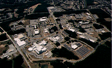
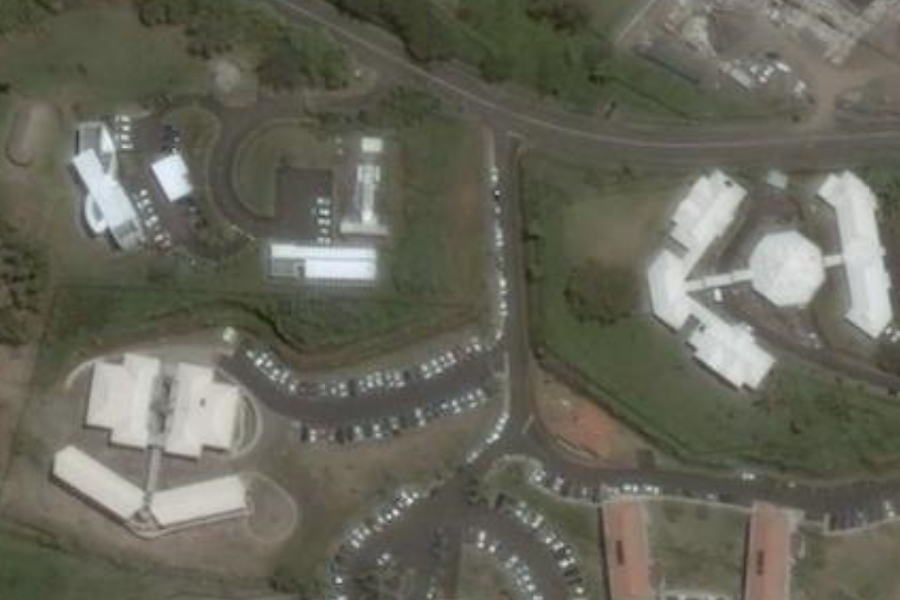
The Goddard Geophysical and Astronomical Observatory (GGAO) is the home of pioneering research in many scientific areas. Scientific application of lasers, astronomy, and solar physics, are just a few examples. The 210-acre facility is located four miles from the GSFC main site on Springfield Road. It is home to about a dozen people working on many NASA research projects. It was formerly called the Goddard Optical Research Facility (GORF) and was originally established to provide a low background (light) level for optical instrumentation development and observation. Due to its remote location from the main Goddard site, the activities performed there are not known by most people at GSFC. The Solar System Exploration Division (Code 690) at NASA GSFC uses GGAO for Satellite Laser Ranging (SLR), Very Long Baseline Interferometry (VLBI), global navigation satellite system (GNSS, including GPS, Global Positioning System and GLONASS, GLObal NAvigation Satellite System) and DORIS (Doppler Orbitography by Radiopositioning Integrated on Satellite) activities. GGAO is one of the few locations in the world where four or more space geodesy techniques are co-located, thus providing scientists with a unique opportunity to assess system performance and perform multi-technique analysis. Other divisions in Code 600 also use the GGAO facility for various astronomy-related activities. |
|||||||||||
|
International DORIS Service ..
DORIS is a Doppler satellite tracking system developped for precise orbit determination and precise ground location. It is onboard the Jason-1 and ENVISAT altimetric satellites and the remote sensing satellites SPOT-2, SPOT-4 and SPOT-5. It also flew with SPOT-3 and TOPEX/POSEIDON. IDS is an international service which provides a support, through DORIS data and products, to geodetic, geophysical, and other research and operational activities. New proposals for Analysis Centers and temporary or permanent DORIS stations are welcome. See the call for participation. |
|||||||||||
|
Electro Optic Systems (EOS) ..
EOS develops and produces products incorporating advanced electro-optic technologies for the aerospace market. EOS products are developed through internal research and development programs based on EOS core technologies in software, lasers, electronics, optics, gimbals, telescopes and beam directors, optical coatings and precision mechanisms. EOS focuses on the space surveillance and control, and the military force protection sectors of the aerospace market. In space surveillance and control, EOS specializes in space information based on the use of EOS-developed instruments and sensors to detect, track, classify and charaterise objects in space. This information is required for both military and commercial space applications. To support its space business, EOS develops and produces a wide range of space-related infrastructure in the form of sub-systems, such as telescopes and beam directors. Some of these are sold commercially. An example is optical telescopes, where EOS is widely known as the largest producer of major optical telescopes in the world. In 2005 EOS formed a strategic alliance with Northrop Grumman [USA] for the development and exploitation of certain segments of the space sector. In the force protection sector, EOS develops and produces complete robotic or remotely-controlled weapon systems, based on existing weapons in customer inventory. This market is addressed by EOS through a range of activities, as both prime and sub-contractor, and in partnership with other entities active in the sector. The US Army CROWS program is a major program where EOS participates as a sub-contractor to Recon optical Inc. EOS operates research centres in Australia, the US and Germany, and has significant production facilities in Australia and the US. New production facilities are expected to come on line in Germany in 2007 to meet demand from both space and weapons sectors. The EOS Group of companies was founded in 1983 and became a publicly-traded company on the Australian Stock Exchange in 2002. |
|||||||||||
|
NASA SLR2000 ..
Facts about SLR2000
|
|||||||||||
| FAIR USE NOTICE: This page contains copyrighted material the use of which has not been specifically authorized by the copyright owner. Pegasus Research Consortium distributes this material without profit to those who have expressed a prior interest in receiving the included information for research and educational purposes. We believe this constitutes a fair use of any such copyrighted material as provided for in 17 U.S.C § 107. If you wish to use copyrighted material from this site for purposes of your own that go beyond fair use, you must obtain permission from the copyright owner. | |||||||||||
|
|

