COSMIC SECRETS
The Enigmas on Mars 56
|
Phoenix
Landing
Color Image of
Phoenix Parachute
on Mars Surface
05.27.08
..
Credit:
NASA/JPL-Caltech/University
of Arizona
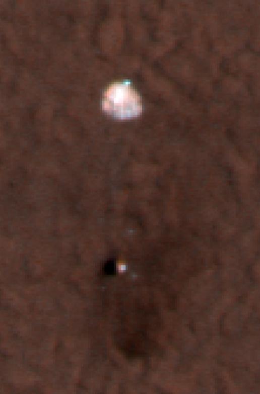
This shows a color image
from Mars Reconnaissance
Orbiter's High Resolution Imaging
Science Experiment camera. It shows the
Phoenix parachute top attached to the
back shell bottom on the Mars surface.
In this image, north is down.
The Phoenix Mission is
led by the University of Arizona,
Tucson, on behalf of NASA. Project
management of the mission is by NASA's
Jet Propulsion Laboratory, Pasadena,
Calif. Spacecraft development is by
Lockheed Martin Space Systems, Denver.
Image
NASA/JPL-Caltech/University of Arizona
SOURCE: NASA
Phoenix
Mission
|
Phoenix Landing
Camera on Mars
Orbiter Snaps
Phoenix During Landing
Phoenix Makes a
Grand Entrance
2008-05-26
..
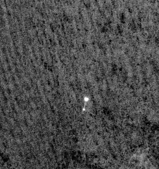
NASA's
Mars Phoenix Lander
can be seen parachuting down to Mars, in this
image captured by the Mars
Reconnaissance Orbiter. Image credit:
NASA/JPL-Caltech/University of Arizona
NASA's Phoenix
Mars Lander can
be seen parachuting down to Mars, in this image
captured by the High Resolution
Imaging Science Experiment (HiRISE) camera on
NASA's Mars Reconnaissance
Orbiter. This is the first time that a spacecraft
has imaged the final
descent of another spacecraft onto a planetary
body.
From a
distance of about 310
kilometers (193 miles) above the surface of Mars,
Mars Reconnaissance Orbiter
pointed its HiRISE camera obliquely toward Phoenix
to capture this shot.
Phoenix had just opened its parachute 46 seconds
earlier, jettisoned its
heat shield and was two minutes and 52 seconds
away from landing on the
Red Planet. The image reveals the parachute and a
dangling Phoenix below.
The chords attaching the spacecraft's back shell
and parachute are faintly
visible. The surroundings look dark, but
correspond to the fully illuminated
Martian surface, which is much darker than the
parachute and back shell.
Phoenix
released its parachute
at an altitude of about 12.6 kilometers (7.8
miles).
The HiRISE,
acquired this image
on May 25, 2008, at 4:36 p.m. Pacific Time (7:36
p.m. Eastern Time). It
is a highly oblique view of the Martian surface,
26 degrees above the horizon,
or 64 degrees from the normal straight-down
imaging of Mars Reconnaissance
Orbiter. The image has a scale of 0.76 meters per
pixel.
This image has
been brightened
to show the patterned surface of Mars in the
background.
NASA's Jet
Propulsion Laboratory,
a division of the California Institute of
Technology in Pasadena, manages
the Mars Reconnaissance Orbiter for NASA's Science
Mission Directorate,
Washington. Lockheed Martin Space Systems, Denver,
is the prime contractor
for the project and built the spacecraft. The High
Resolution Imaging Science
Experiment is operated by the University of
Arizona, Tucson, and the instrument
was built by Ball Aerospace & Technologies
Corp., Boulder, Colo.
NASA/JPL-Caltech/University
of
Arizona
SOURCE: NASA
Phoenix
Lander
Phoenix
Descent with Color and
the Heat Shield in Free-Fall
(PSP_008579_9020-B)
Credit: NASA/JPL/University of
Arizona
HiRISE acquired
this now
famous
image of the Phoenix Lander during its descent
through the atmosphere.
The lander was still inside the backshell hanging
from its parachute at
the moment this image was taken. It was an
engineering triumph to capture
the lander within the HiRISE field of view. We had
hoped for it to be within
the color portion of the HiRISE camera, but
unfortunately it missed that
area.
For this reason, processing the
color bands did not
take a high priority in the days following
acquisition of this image. The
unusual geometry of the image prevented the color
processing from running
through the automated software pipelines. It had to
be processed "by hand"
which means processing parameters were adjusting
manually until good registration
of the color bands was achieved.
Normally, the 10 CCDs that span the
HiRISE image area
overlap by 48 pixels at their edges. The gaps in the
image are due to the
fact that Mars surface was moving through the HiRISE
field of view at an
angle, which also caused some image smear. (The slew
was designed to get
an unsmeared image of the parachute.) Some CCDs have
gaps between them,
while others overlap more than usual. Map
projection
takes the image and transforms it so it looks
like you are
looking straight down at the surface. The lander is
very distorted in the
map
projection, because it is not actually on the
surface.
In
the
non-map projected image, the gaps have been
closed to make a more
aesthetic image. Some discontinuities are visible
along the seams between
CCDs where this has been done.
The color does give some more
information about the
crater. There is frost or ice in the bowl of the
crater which shows up
as blue in the false color HiRISE data. Here the
color has been adjusted
for a more natural appearance. The frost is visible
in the right side of
the non-projected image.
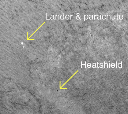
The Phoenix Lander discarded its
heat shield after
deploying the parachute. Scientists and engineers at
JPL believe that the
heat shield should also be visible in this image.
After some analysis,
the small
dark
dot located below the lander looks like a
stong candidate for
the heat shield. It is in the right location based
on descent trajectories
and timing.
..
The Phoenix
Lander discarded
its heat shield after deploying the parachute.
Scientists and engineers
at JPL believe that the heat shield should also be
visible in this image.
After some analysis, the small dark dot located
below the lander looks
like a stong candidate for the heat shield. It is
in the right location
based on descent trajectories and timing.
Image credit: NASA/JPL-Caltech/University
of Arizona
Another sign that the small dark
spot is the heat shield
is that its pixel value is lower than any other dark
spot in the vicinity.
The lander is approximately 20 kilometers in front
of the crater, so there
is at least 20 km less atmosphere between the HiRISE
camera and the lander
and heat shield than between the camera and the
surface. The size is right,
too. The heat shield protected the bottom of the
lander through atmospheric
entry, so its external surface would be a charred
black. It is visible
in the images taken of the actual landing
site.
SOURCE: HiRISE
Page
|
Descent of the
Phoenix Lander
HiRISE Image
(PSP 008579
9020)
..
NASA/JPL-Caltech/University
of
Arizona
..
NASA/JPL-Caltech/University
of
Arizona
MRO's HiRISE
camera acquired this
dramatic
oblique image of Phoenix descending on its
parachute. Shown
here is a a wider view of the full image, showing a
10 kilometer diameter
crater informally called "Heimdall" and an improved
full-resolution image
of the parachute and lander.
Although it appears that Phoenix is
descending into
the crater, it is actually about 20 kilometers in
front of the crater.
It is difficult to believe that it is in front of
the crater because it
is so much smaller, but in reality it is, and that's
a good thing because
landing on the steep rocky slopes of the crater
would have been far too
exciting (or risky).
Images from the lander clearly show
that it sits on
a flat plain, although the rim of Heimdall may be
visible on the horizon.
Given the position and pointing angle of MRO,
Phoenix is at about 13 km
above the surface, just a few seconds after the
parachute opened. This
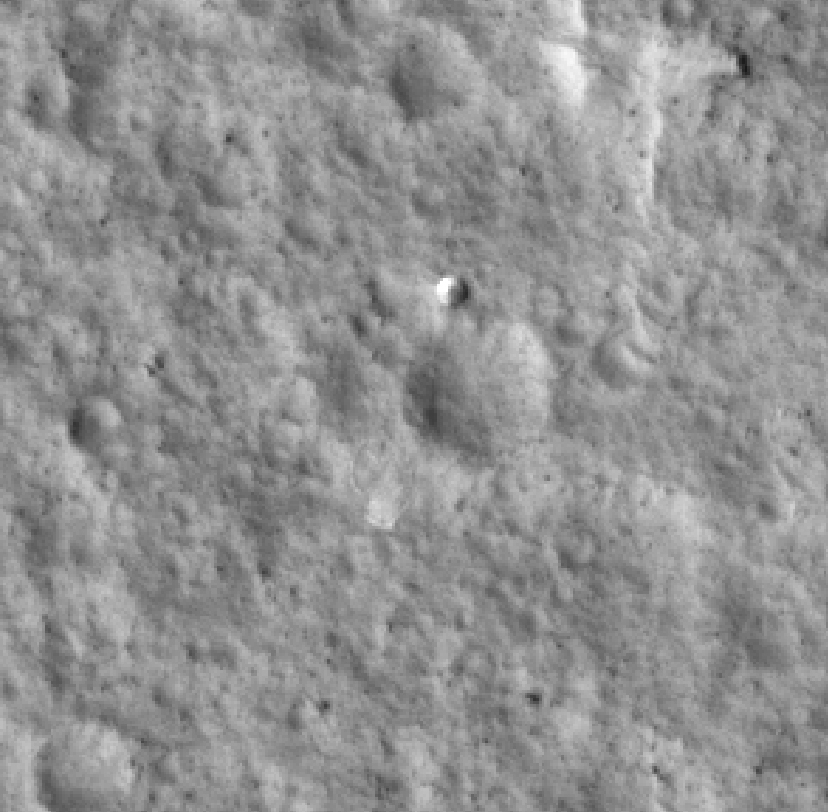
improved image shows some details of the parachute,
including the gap between
upper and lower sections. At the time of this
observation, MRO had an orbital
altitude of 310 km, traveling at a ground velocity
of 3.4 kilometers/second,
and a distance of 760 km to the Phoenix
lander.
The image was rotated to a position
that seems approximately
parallel to the horizon based on the elongation of
Heimdall crater, but
this is not exact. Thus, although Phoenix appears to
hang from the parachute
at an angle, as if swaying in the wind, the exact
geometry has not yet
been determined. The parachute image is very sharp
as its apparent motion
was straight down the HiRISE TDI (time delay
integration) columns. However,
the surface of Mars was moving at an angle to the
TDI columns, and thus
is smeared by a few pixels, although the smear is
not apparent at the reduced
scale of the image shown here.
SCALE INFORMATION
Map projected scale: No map projected
products
Original image scale range: 0.792712
cm/pixel
UNANNOTATED IMAGES
For those interested in larger,
unannotated versions,
you may select a TIF image here:
PSP_008579_9020
(2048
samples x 1019 lines; 4MB)
PSP_008579_9020
(4096
samples x 2038 lines; 16MB.)
PSP_008579_9020
Parachute
insert (756KB)
TIFF WITH INSET
A TIFF version of the descent image
with its inset
is PSP_008579_9020_descent
(4096x2038; 24 MB)
ADDITIONAL PRODUCTS AND COLOR
HiRISE has managed to produce a
version of this image
with
a
color swath.
*NOTE ON NOMENCLATURE
When this caption was written, the
name "Heimdall"
(with the double "L") was an informal one. Since
then, the International
Astronomical Union (IAU)
has officially
named the crater "Heimdal" with one "L." We decided
to keep the original
spelling in the caption as part of the historical
moment of this incredible
image.
SOURCE: HiRISE
Page - HiRISE
Image
|
Phoenix Lander
Hardware
EDL +11
(PSP 008585 2915)
11 Hours after
landing
..
NASA/JPL-Caltech/University
of
Arizona
..
NASA/JPL-Caltech/University
of
Arizona {click image for full size}
MRO's HiRISE
camera acquired this
image of the Phoenix landing site 11 hours after
landing. The image shows
three unusual features, which were not present in
the earlier, pre-landing
HiRISE image.
We expect to find three
main
pieces of hardware: the parachute attached to
the backshell, the
heat shield, and the lander itself. The parachute
(lower right) is easy
to identify because it is especially bright,
although this image doesn't
clearly reveal the backshell.
The double dark marking at upper
right seems most consistent
with disturbance of the ground from impact and
bouncing of the heat shield,
which fell from a height of about 13 kilometers.
The last object (upper left) appears
to be a about
the right size and height for the lander, and with
dark objects on each
side (to the east and west) consistent with the
solar arrays.
This image was acquired in the
nighttime, when the
arctic sun was only 12 degrees above the horizon to
the northeast. Later
images will be acquired in the daytime with the sun
higher in the sky and
to the southwest, and could confirm our initial
interpretations. North
is about 7 degrees to the left of straight up in
this image.
These objects were later confirmed
on the subsequent
HiRISE observation acquired
22
hours after landing.
SCALE INFORMATION
Map projected
scale: = 0.25
Original image scale
range:
= 0.314742 cm/pixel
SOURCE: HiRISE
Page
|
Phoenix Lander
Hardware
EDL +22
(PSP 008591 2485)
22 Hours after
landing
..
NASA/JPL-Caltech/University
of
Arizona
..
NASA/JPL-Caltech/University
of
Arizona {click image for full size}
MRO’s HiRISE
camera acquired this
image
of the Phoenix landing site 22 hours after
landing. The image
shows three unusual features; seen also is the image
acquired
11 hours after landing. These three features
were not present
in a pre-landing HiRISE image.
We expect to find three main pieces
of hardware: the
parachute
attached
to the backshell, the heat
shield, and the lander
itself.
The parachute (bottom)
is easy to identify because it is especially bright,
and this image also
clearly shows the backshell. We can even see the
stripes on the parachute.
The dark marking (middle
right) appears most consistent with
disturbance of the ground from
impact and bouncing of the heat shield, which fell
from a height of about
13 kilometers.
The last object (top)
is the lander, and we can clearly see the solar
arrays on each side. The
solar arrays were relatively dark in the image
acquired 11 hours after
landing, but are brighter than the Mars surface in
this daytime image acquired
with the HiRISE blue-green filter.
There are dark halos around all
three locations, perhaps
due to disturbing a thin dust coating. North is
about 7 degrees to the
right of straight up in this image and illumination
is from the lower left.
ANAGLYPH IMAGE
HiRISE has created an anaglyph
image of the landing site.
SCALE INFORMATION
Map projected
scale: = 0.25
Original image scale
range:
= 0.34551 cm/pixel
SOURCE: HiRISE
Page
|
Anaglyph of the
Phoenix Landing
Site
(PSP 008644
2485)
..
NASA/JPL-Caltech/University
of
Arizona
These anaglyph
images reveal the
Phoenix landing site to have uniform terrain with
little topographic relief.
However, it is possible to see some terrain
differences.
The parachute
and
backshell anaglyph shows the backshell
projecting up above the
surrounding terrain explaining why it is visible in
images from the Phoenix
Lander SSI camera. The parachute is flat on the
surface and situated in
a small depression making it unseen by the SSI.
The Phoenix
Lander
anaglyph shows the Lander also projecting
above the surrounding
terrain. A topographic rise is visible to the left
of the lander. The troughs
and bulges of the polygonal terrain can also be
seen.
A larger view of the Phoenix landing
site is available
here. The topographic relief is exaggerated
because of the large differences
in look angles (approximately 27 degrees) between
the two images (PSP_008644_2485
and PSP_008591_2485)
that make up the anaglyph. The anaglyph images
maintain the original viewing
geometry with north down.
SCALE INFORMATION
Map projected
scale: = 0.25
Original image scale
range: = 0.313812
cm/pixel
SOURCE: HiRISE
Page
|
Opportunity
Rover
February 21,
2009
..
This amazing
image, taken from
Mars orbit, shows one of NASA's rovers on the
surface of the Red Planet.
Look at the larger image (below) to get a good
idea of the surrounding
terrain.
..
Credit:
NASA/JPL
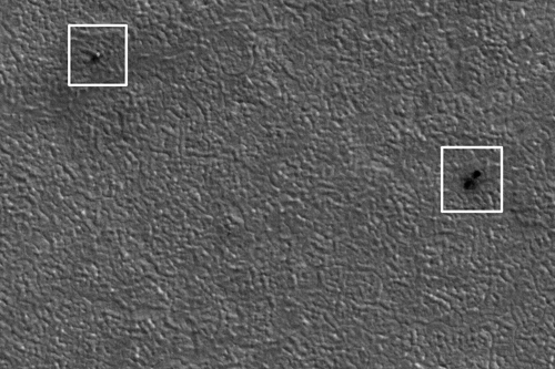
The image
above was taken from
Mars orbit by the Mars Reconnaissance Orbiter
(MRO) spacecraft. It spans
about 400 metres across the surface of the Red
Planet, and shows the Mars
rover Opportunity as a small black dot (circled at
lower left).
The image was
taken during the
afternoon of Opportunity's 1,783rd sol (Mars day)
on the Red Planet. Opportunity
had driven 130 metres on the previous sol; you can
see wheel tracks crossing
dark dune ripples to the upper right of the rover.
The ripples, which trend
mostly north-south in this area, can be easily
crossed by the rover unless
they are very large (such as those right of
centre).
The
availability of MRO images
of the terrain that Opportunity is crossing allow
traverses to be planned
in detail, avoiding potential hazards and
targeting features of interest
(such as the small craters below and left of
centre).
MRO images are
routinely used
by the Opportunity operations team for these
purposes, and to plan the
route to distant Endeavour Crater, the long-term
goal of Opportunity's
mission, about 17 kilometres to the southeast.
The
full-circle image below (made
up of a mosaic of multiple images) was taken by
Opportunity only days after
MRO photographed it from above. Opportunity used
its navigation camera
to take the images combined into this view of the
rover's surroundings
just after driving 60.86 metres (200 feet) on the
1,806th sol of its surface
mission (February 21, 2009).
SOURCE: Spaceinfo.com.au
|
Opportunity
Rover
Mars
Reconnaissance Orbiter
spots rover’s landing site
November 29,
2006
..
NASA /
JPL / MSSS
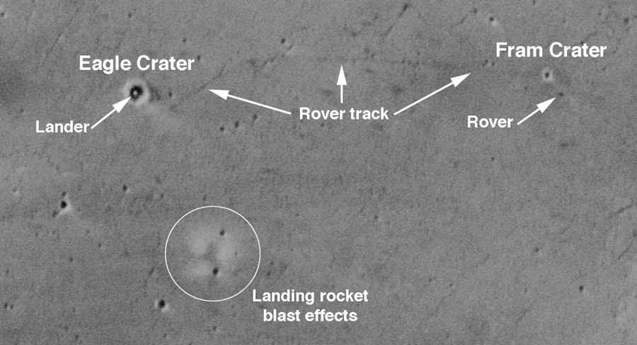
A photo taken
from orbit by NASA's
Mars Global Surveyor shows Opportunity's landing
site and its tracks through
Meridiani Planum, ending at the rover itself,
visible as a speck. The rover's
landing platform also can be seen within Eagle
Crater. - One
amazing
year for Opportunity rover - MSNBC
..
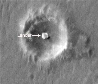
NASA /
JPL / MSSS
Mars orbiter
spots rover’s landing
site. Mars Reconnaissance Orbiter image shows
“Eagle crater," the small
impact crater where Opportunity’s lander came to
rest. The image is one
of a gallery of photos released by NASA on
Wednesday. - Mars
orbiter
spots rover’s landing site - MSNBC
|
Opportunity
Rover
PIA05230: 'You
Are Here'
Mars Global
Surveyor
January 24,
2004
..
NASA /
JPL / MSSS
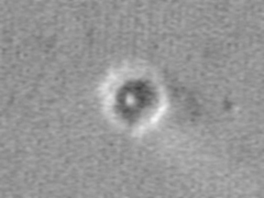
This map shows
the Mars Exploration
Rover Opportunity and its lander on the surface of
Mars. The robotic geologist
landed inside a small crater at Meridiani Planum
on Jan. 24, 2004, PST.
The white spot is the lander, and the small black
spot northeast of it
is believed to be the rover (see
inset). The image was taken by the camera
onboard the Mars Global Surveyor
orbiter.
Image Addition
Date: 2004-02-09
SOURCE: NASA
Photo
Journal PIA05230
|
Spirit Rover
PIA03255:
Spirit on "Husband
Hill,"
Mars Global
Surveyor
November 2,
2005 with January
10, 2004 Comparison
..
Image
Credit: NASA/JPL-Caltech/MSSS
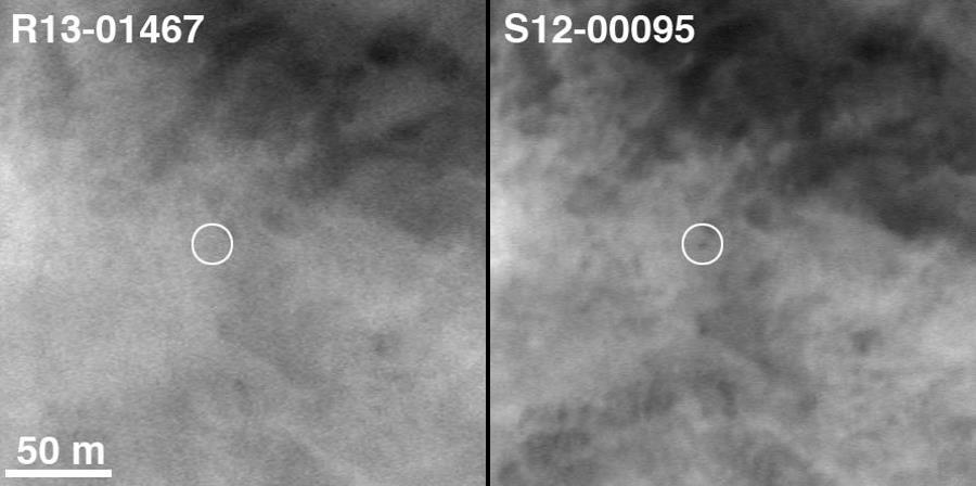
Two Earth
years ago, NASA's Mars
Exploration Rover Spirit touched down in Gusev
Crater. The rover marked
its first Mars-year (687 Earth days) anniversary
in November 2005. On Nov.
2, 2005, shortly before Spirit's Martian
anniversary, the Mars Orbiter
Camera on NASA's Mars Global Surveyor acquired an
image centered on the
rover's location in the "Columbia Hills." The
location of Spirit on that
date is circled on the image on the right. On the
left, for comparison,
is an image from Jan. 10, 2004, when few dreamed
that the Spirit would
ever reach the hills from its landing site about
three kilometers (two
miles) away.
The newer
image has a resolution
of about 50 centimeters (1.6 feet) per pixel.
North is up; illumination
is from the left. The location is near 14.8
degrees south latitude, 184.6
degrees west longitude. Dr. Timothy J. Parker of
the Mars Exploration Rover
team at NASA's Jet Propulsion Laboratory,
Pasadena, Calif., confirmed the
location of the rover in the 2005 image. The scale
bar is 50 meters (164
feet).
Image Addition
Date: 2006-01-03
SOURCE: NASA
Photo
Journal PIA03255
|
PIA01881:
Viking Lander 1
(Thomas A.
Mutch Memorial Station)
Imaged from
Orbit
..
Viking
1 Lander - Mars
Reconnaissance Orbiter
Image
Credit: NASA/JPL-Caltech/University
of Arizona
NASA's Viking
Lander 1 touched
down in western Chryse Planitia on July 20, 1976.
The lander, which has
a diameter of about 3 meters (10 feet), has been
precisely located in this
image from the High Resolution Imaging Science
Experiment camera on NASA's
Mars Reconnaissance Orbiter. Also, likely
locations have been found for
the heat shield, back shell, and parachute
attached to the back shell.
The lander location has been confirmed by
overlaying the lander-derived
topographic contours on the high-resolution
camera's image, which provides
an excellent match. Viking Lander 1 was one
element of an ambitious mission
to study Mars, with a four-spacecraft flotilla
consisting of two orbiters
and two landers. Four cutouts from this image are
shown. The first is an
overview showing the relative locations of the
lander and candidate back
shell and heat shield, and the others are
enlargements of each of these
components. Large boulders, dunes, and other
features visible in Lander
images can be located in the image.
..
Viking
1 Backshell and
Parachute (white patch in center) - Mars
Reconnaissance Orbiter
Image
Credit: NASA/JPL-Caltech/University
of Arizona
A prime
motivation for early
viewing of these Viking sites is to calibrate
imagery taken from orbit
with the data previously acquired by the landers.
In particular, determining
what sizes of rocks can be seen from Mars
Reconnaissance Orbiter aids the
interpretation of data now being taken to
characterize sites for future
landers, such as the Phoenix Mars Lander mission
to be launched in 2007.
..
Viking
1 Heat Shield
- Mars Reconnaissance Orbiter
Image
Credit: NASA/JPL-Caltech/University
of Arizona
Images from
the High Resolution
Imaging Science Experiment and additional
information about the Mars Reconnaissance
Orbiter are available online at: http://www.nasa.gov/mro
or
http://HiRISE.lpl.arizona.edu
NASA's Jet
Propulsion Laboratory,
a division of the California Institute of
Technology in Pasadena, manages
the Mars Reconnaissance Orbiter for NASA's Science
Mission Directorate,
Washington. Lockheed Martin Space Systems is the
prime contractor for the
project and built the spacecraft. The High
Resolution Imaging Science Experiment
camera was built by Ball Aerospace Corporation and
is operated by the University
of Arizona.
Image Addition
Date: 2006-12-05
..
Viking
1 Annotated
full
version - Mars Reconnaissance Orbiter
Image
Credit: NASA/JPL-Caltech/University
of Arizona
SOURCE: NASA
Photo
Journal PIA01881
|
PIA01882:
Viking Lander 2
Imaged from
Orbit
..
Viking
2 Lander - Mars
Reconnaissance Orbiter
Image
Credit: NASA/JPL-Caltech/University
of Arizona
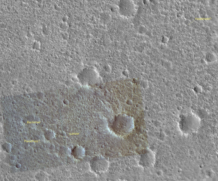
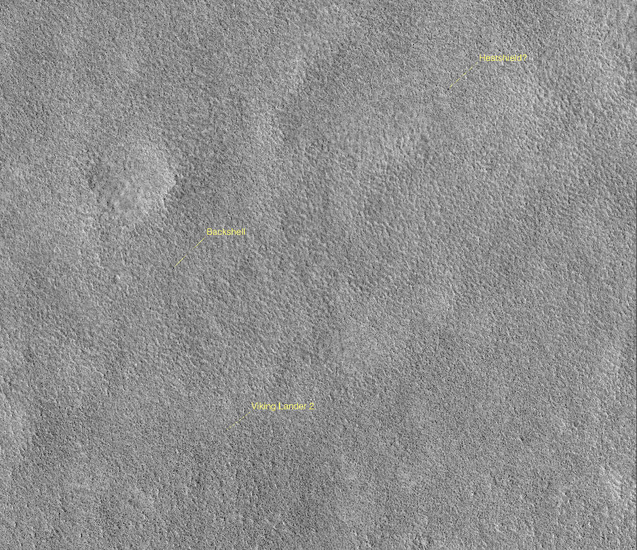
NASA's Viking
Lander 2 landed
on Mars on Sept. 3, 1976, in Utopia Planitia. The
lander, which has a diameter
of about 3 meters (10 feet), has been precisely
located in this image from
the High Resolution Imaging Science Experiment on
NASA's Mars Reconnaissance
Orbiter. Also, likely locations have been found
for the heat shield and
back shell. The lander location has been confirmed
by overlaying the lander-derived
topographic contours on the high-resolution
camera's image, which provides
an excellent match. Viking Lander 2 was one
element of an ambitious mission
to study Mars, with a four-spacecraft flotilla
consisting of two orbiters
and two landers. Four cutouts from this image are
shown. The first is an
overview showing the relative locations of the
lander and candidate back
shell and heat shield, and the others are
enlargements of each of these
components. Large boulders, dunes, and other
features visible in Viking
Lander 2 images can be located in the
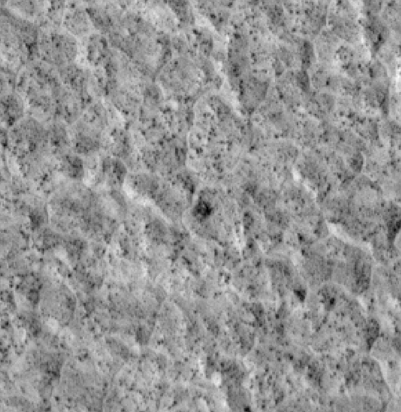
high-resolution camera's image. The
polygonal pattern of the surface is typical at
these latitudes and may
be due to the presence of deep subsurface ice.
..
Viking
2 Backshell -
Mars Reconnaissance Orbiter
Image
Credit: NASA/JPL-Caltech/University
of Arizona
As chance
would have it, this
image is blurred in some places due to the abrupt
motion associated with
the restart of the orbiter's high-gain antenna
tracking during the very
short image exposure. This is the first time after
acquiring hundreds of
pictures that a High Resolution Imaging Science
Experiment image has been
unintentionally smeared; overall performance has
been excellent.
..
Viking
2 Heat Shield
- Mars Reconnaissance Orbiter
Image
Credit: NASA/JPL-Caltech/University
of Arizona
A prime
motivation for early
viewing of the Viking sites is to calibrate
imagery taken from orbit with
the data previously acquired by the landers. In
particular, determining
what sizes of rocks can be seen from Mars
Reconnaissance Orbiter aids the
interpretation of data now being taken to
characterize sites for future
landers, such as the Phoenix Mars Lander mission
to be launched in 2007.
Image Addition
Date: 2006-12-05
..
Viking
2 Annotated
full
version - Mars Reconnaissance Orbiter
Image
Credit: NASA/JPL-Caltech/University
of Arizona
SOURCE: NASA
Photo
Journal PIA01882
|
| Related Links:
|
| FAIR USE
NOTICE: This page contains copyrighted
material the use of which has not been specifically
authorized by the copyright
owner. Pegasus Research Consortium distributes this
material without profit
to those who have expressed a prior interest in
receiving the included
information for research and educational purposes. We
believe this constitutes
a fair use of any such copyrighted material as
provided for in 17 U.S.C
§ 107. If you wish to use copyrighted material from
this site for
purposes of your own that go beyond fair use, you must
obtain permission
from the copyright owner. |
|
~ MENU
~
|
